A poorly designed pneumatic conveying system is a financial drain. It creates a cycle of unplanned shutdowns, excessive energy consumption, and product degradation that can haunt a facility for decades.
For the professionals responsible for these systems, the design phase is the only window of opportunity to prevent these recurring technical failures. Whether you’re troubleshooting a line that keeps choking or specifying components for a new capital project, understanding the physics of material movement is how you protect your uptime.
This Roto-Disc guide provides a detailed look at pneumatic conveying system sizing. We’re moving past basic surface-level checklists to explore the math, material variables, and specific hardware choices that determine whether a system will thrive under real-world industrial loads.
Why Do Pneumatic Conveying Systems Fail to Meet Their Rated Capacity?
The main challenge when designing pneumatic conveying systems is balancing the air-to-solids ratio. If you have too much air, you waste power and destroy your equipment through abrasive wear. If you have too little air, your material settles and creates a plug that can take hours of manual labor to clear.
Industrial environments are rarely as clean as a laboratory. You deal with humidity fluctuations that make powders sticky, variations in bulk density, and abrasive particles that erode standard valves.
A consultant-level approach to sizing means anticipating these variables before the first pipe is hung. You’re not just moving material: you’re managing a pressure environment where every component must act as a reliable seal.
What Specific Material Data Points Change Your Pneumatic Conveying Calculations?
You cannot build a system based on average material behavior. To get a successful design, you need to start by digging into the bulk solids you’re moving. If you guess at this stage, the system will fail under pressure later.
Analyzing Bulk Density: Your First Reality Check
Bulk density, measured in pounds per cubic foot, is the primary variable used to calculate the energy required to entrain particles in an air stream.
But density is only the starting line. You must also account for particle shape and size distribution. You get a predictable flow when the pellets are uniform, but the jagged, irregular shapes of some minerals disrupt consistency, leading to inconsistent drag and turbulence.
For engineers managing spices, specialty chemicals, or pharmaceutical powders, moisture is the silent enemy. Sticky materials don’t just flow: they smear and pack inside traditional valves, which throws off the pressure balance of the entire system.
If your sizing calculations ignore the tackiness of your product, you’re designing a system that is guaranteed to clog.
Managing Abrasiveness: The Mechanical Sandblaster
In mining, aggregate, or glass manufacturing, the primary sizing goal is survival. High-velocity air moving abrasive glass batch, or coal ash, acts like a mechanical sandblaster inside your pipelines.
Proper sizing allows you to move these materials at the lowest possible velocity, safeguarding your pipe walls and valve seats from premature erosion. Roto-Disc engineers solutions for these severe wear conditions.
How Do You Choose Between Dilute Phase and Dense Phase Conveying?
The choice between dilute phase and dense phase conveying sets the foundation for your entire system.
- Dilute Phase Conveying: This involves high-velocity air, with the material fully suspended in the stream. It’s often used for non-abrasive materials. It requires lower pressure but higher air volume.
- Dense Phase Conveying: This uses lower velocity and higher pressure to move material in slugs or waves. This is the preferred method for abrasive materials or fragile products that cannot handle high-impact collisions with pipe walls.
Selecting the wrong mode often leads to product breakage or equipment failure. If your material is friable, a high-velocity dilute system will turn your product into dust before it reaches the destination.
If your material is heavy and abrasive, like coal or sand, the dilute phase will erode your elbows and valves in weeks.
What Are the Core Steps to Sizing a Pneumatic Conveying System Correctly?
To move from a concept to a functional installation, you must apply rigorous pneumatic conveying calculations. These figures dictate the horsepower of your blower, the diameter of your piping, and the sealing requirements of your airlocks.
1. Finding the Invisible Floor: Saltation and Pickup Velocity
Saltation velocity is the minimum air speed required to keep particles suspended in a horizontal pipe. If the velocity drops below this floor, the material settles and the line plugs.
To build in a safety margin, experienced designers target a pickup velocity that is 20% to 30% higher than the saltation velocity. The relationship for gas velocity is often calculated using:
2. Solving the Pressure Drop Equation
Every bend, vertical lift, and valve in your system is a source of friction. You must calculate the total pressure drop to size your blower correctly. For straight pipe sections, the Darcy-Weisbach equation is a standard starting point:
Underestimating this figure is a common cause of systems that stall the moment they are pushed to their rated capacity.
3. Calculating the Solid Loading Ratio
This is the ratio of the mass flow rate of the solids to the mass flow rate of the air. It is expressed as:
A high ratio is energy-efficient because you move more product with less air, but it is also high-risk. High-density flow requires significant pressure to maintain movement. If your pipe diameter is too small for your chosen ratio, the friction will skyrocket, and the system will stop.
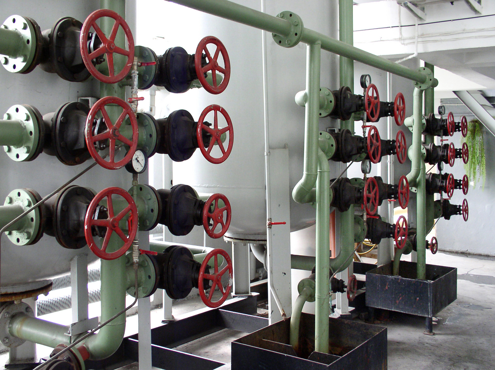
Why Is the Feed Valve the Most Overlooked Variable in System Design?
In many discussions of pneumatic conveying system design, the valve is treated as a minor hardware choice. This is a critical error. The valve acts as the gatekeeper for the system’s pressure boundary. If the valve fails to seal, your calculations are no longer valid.
Don’t Ignore Air Leakage at the Pressure Boundary
Standard rotary airlocks are built with small clearances between the rotor and the housing. As the valve handles material, these clearances widen.
This creates air leakage that blows back into the feed hopper. This leakage does two things: it reduces the air available in the pipe to move material, and it creates upward pressure that causes material to bridge in the hopper.
If your rotary valve leakage is high, the air velocity in your pipe will be lower than what your math predicted. This leads to frequent, expensive line plugs that no amount of blower adjustment can fix.
The Roto-Disc Difference: Sealing Air Where It Belongs
When your application requires a true seal, traditional catalog valves often fall short. Roto-Disc designs components specifically for these difficult pressure environments.
The Roto-Flate® Inflatable Seal Valve: This valve uses an inflatable seal to create a bubble-tight barrier. It ensures that 100 percent of your calculated air stays in the pipe where it is needed rather than escaping through the valve.
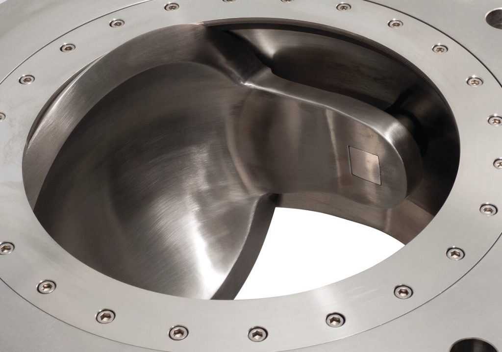
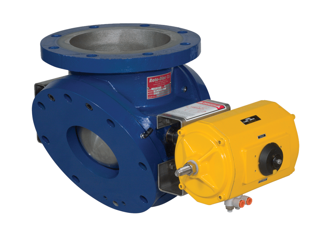
Heavy Duty Spherical Valves: For materials that would grind down the clearances of a rotary airlock, the Roto-Disc® design cuts through the material stream, creating a metal-to-metal seal that maintains its integrity for thousands of cycles.
Double Dump Airlocks: The Roto-Vert®-Flate configuration provides a true airlock that withstands extreme pressure differentials while virtually eliminating back leakage, which destroys system efficiency.

How Does Your Specific Industry Change the Design Math?
Solving Downtime in Heavy Maintenance Operations
In heavy industrial settings, success is measured by the length of time between repairs. When you’re sizing a pneumatic conveying system, you are really sizing your future workload.
Selecting a Roto-Disc® valve for abrasive or high-pressure points reduces the frequency of your rebuild cycles. By maintaining a consistent pressure profile, you avoid the surge and plug cycles that fatigue your equipment and deplete your maintenance budget.
Protecting Integrity in Process and Quality Standards
In the food, beverage, and chemical sectors, your design must prioritize batch integrity. The Roto-Clean® Sanitary Spherical Valve is designed to withstand aggressive washdowns while maintaining the vacuum or pressure integrity of your process.
When you calculate your system throughput, you must factor in the time saved by a valve that’s easy to disassemble and validate for sanitation.
Engineering Precision for Systems Integration
When you build a system for a client, your reputation is attached to its performance during the factory acceptance test. You need components that integrate perfectly into your CAD models and deliver the performance your calculations promised.
Roto-Disc offers the engineering collaboration and lead time reliability necessary to ensure your system hits its targets on day one without field modifications.
Frequently Asked Questions
Base your decision on your material and your distance. The dilute phase is simpler and better for light, non-abrasive materials over shorter runs. Dense phase is the powerhouse choice for abrasive or fragile materials, as it moves product at lower velocities to minimize wear and breakage.
The most frequent failure is underestimating the air loss from worn feed valves. When air leaks out of the pressure boundary, the velocity in the conveying line drops, leading to settled material and massive blockages. Using a Roto-Disc spherical valve with a positive seal eliminates this risk.
Every elbow in your pipe adds significant equivalent length to your system. A single 90-degree bend can create as much pressure drop as dozens of feet of straight pipe. If your design has multiple direction changes, you must size your blower for a much higher total pressure drop to keep the material moving through the turns.
Yes, Roto-Disc offers valves specifically rated for high-vacuum and high-pressure applications. The Roto-Flate® Inflatable Seal is highly effective for vacuum conveying, creating a bubble-tight barrier that prevents atmospheric air from entering and disrupting the vacuum stream.
Roto-Disc’s® Airlock/Double-Dump valve provides a superior seal for abrasive materials. Rotary valves rely on tight clearances that quickly erode in abrasive service, whereas double dump valves use a cycling action that preserves the sealing surfaces and maintains system pressure long term.

Turn Data Into Durable Systems with Roto-Disc
Roto-Disc specializes in the impossible applications where standard catalog valves fail. If you’re designing a new line or fixing one that refuses to run smoothly, our engineering team is ready to help you match the right valve to your specific system math.
Connect with the Roto-Disc team to discuss your pressure and material requirements, or request a quote to see how we can stabilize your pneumatic conveying performance!